

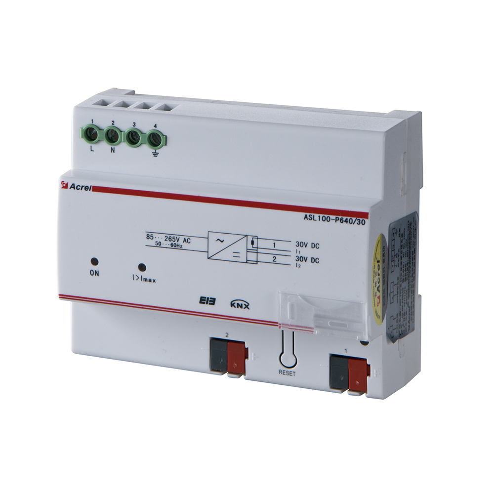


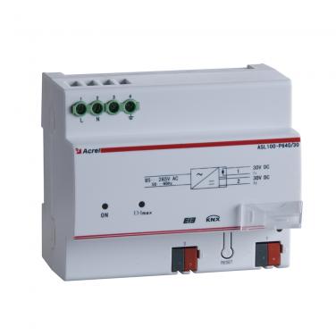
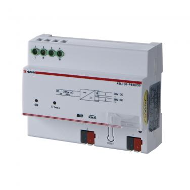

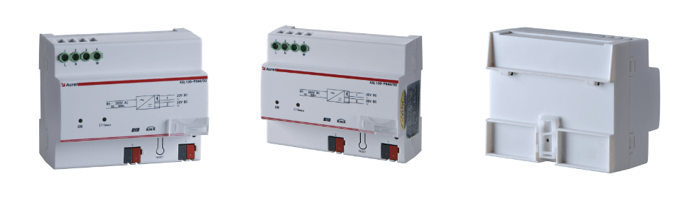
● Model: ASL100-P640/30
● Intelligent lighting control management device
● Power supply for KNX/EIB system
● Input: AC 85~265V; Output: DC30V, 640mA
● Overload protection

General
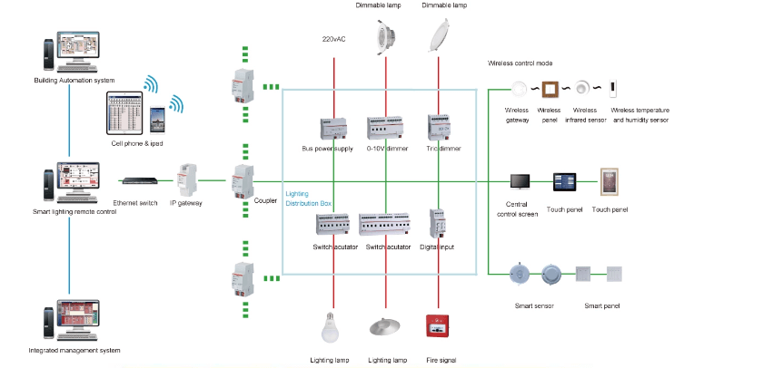
ASL100-P640/30 bus power module (hereinafter referred to as power supply) is a bus power supply based on Acrel-bus intelligent control system. All control modules on the bus are coupled with the power supply by the choker in the power supply.
The bus is connected by the standard EIB wiring terminal and standard KNX bus. After the reset key on the module is pressed, the power supply will be reset for 20s (the bus power supply is disconnected and the auxiliary power supply normally provides the power supply during reset period) and the bus and power supply are disconnected physically. If the power supply needs to be cut off for more than 20s during use, the power line needs to be cut off.
This model of module is also attached with a 30V DC auxiliary output power supply. This auxiliary power supply may power on the external power module, such as IP module and touch screen and so on.
Specification
|
ASL100-P640/30
|
A standard power supply for the KNX/EIB system, coupling bus signals and monitoring overcurrent in KNX/EIB system. Power supply, input: 85~265AC, output: DC30V, 640mA, overload protection. |
|
ASL100-S2/16
|
Switch driver, 2 circuits control.(Max. current: 16A per circuit) |
|
ASL100-S4/16
|
Switch driver, 4 circuits control.(Max. current: 16A per circuit) |
|
ASL100-S8/16
|
Switch driver, 8 circuits control.(Max. current: 16A per circuit) |
|
ASL100-S12/16
|
Switch driver, 12 circuits control.(Max. current: 16A per circuit) |
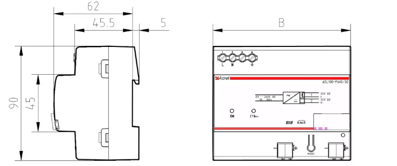
Dimension
Wiring


This module is applicable to 35mm track installation. You just need to clamp the module into the track. It is ok to connect the power input end with the ordinary mains circuit. The grounding symbol is observed on the wiring terminal. Thus, it is suggested to connect the terminal with PE line.
Typical Connection
|
Power input
|
Input voltage
|
85~265V AC
|
|
Power consumption
|
<5W
|
|
|
Efficiency
|
≥75%
|
|
|
Power output
|
Bus power supply
|
30V DC
|
|
Auxiliary power supply
|
30V DC
|
|
|
Output current
|
Bus current+auxiliary current≤640mA
|
|
|
External connection
|
KNX-TP1
|
Use twisted-pair cable conforming to KNX standard
|
|
Wiring terminal at load end
|
Terminating with 0.5nm~0.6nm torque
|
|
|
Operation and display interface
|
Programming key and relevant indicator
|
LED indicator is in red when waiting for programming and is in green during and after programming
|
|
Temperature range
|
Operating temperature
|
-5℃~+45℃
|
|
Storage temperature
|
-25℃~+55℃
|
|
|
Transport temperature
|
-30℃~+70℃
|
|
|
Environment request
|
Maximum air humidity
|
95%
|
|
Dimension(mm)
|
108*90*69mm
|
|
|
Installation
|
Standard 35mm track installation
|
|