
Abstract: This paper introduces the application of Acrel APM series AC meter in the AC side of Bulgarian photovoltaic system. It is mainly used to measure the current in the photovoltaic system, and cooperate with the transformers to measure, communicate and control the circuit system.
1.Project Overview
The company is located in Bulgaria. The company is mainly engaged in the design / installation, construction / maintenance of small photovoltaic power generation center projects in Bulgaria and surrounding countries. The customer wants to use AC meters APM801, APM810 and mutual inductors for monitoring, metering and communication of current and voltage at the AC side of photovoltaic system, and control by using the switching value function of APM meter.
2.APM Series Energy Meter
APM series power meters of ACREL are power meters that are designed according to IEC standards and synchronized with international advanced technology.
APM series meters have full power measurement, energy statistics, analysis of power quality and network communications and other functions, are mainly used for comprehensive monitoring of the quality of power supply network.
This series of meters use a modular design, with a rich function of the external DI / DO module, AI / AO module, event recording (SOE) module with T-Flash (TF) card, network communication module, temperature and humidity measurement module, can achieve full power measurement of electrical circuit and monitoring of switch status, dual RS485 with Ethernet interface can realize data copying of RS485 master station, eliminating the need for data switching exchange. PROFIBUS-DP interface can realize high-speed data transmission and networking function.
3.Type and Function Description
|
Function |
APM800 (Cass 0.5s) |
APM801 (Class 0.2s) |
APM810 (Class 0.5s) |
||
|
Measured Parameters |
Total electrical measurement |
√ |
√ |
√ |
|
|
Four-quadrant energy |
√ |
√ |
√ |
||
|
Pulse output of energy |
Pulse output of active/reactive energy |
√ |
√ |
√ |
|
|
Demand |
Three-phase current, active power, reactive power, real-time demand of apparent power, and maximum demand (including time stamp) |
√ |
√ |
√ |
|
|
Extreme value statistics |
Extremum of current, line & phase voltage, active & reactive power, apparent power, power factor, frequency, total harmonic of current, total harmonic of voltage in this month and last month (including time stamp) |
√ |
√ |
√ |
|
|
Power quality |
Unbalance of current, line voltage, phase voltage |
√ |
√ |
√ |
|
|
Voltage phase angle, current phase angle |
√ |
√ |
√ |
||
|
Voltage current phase Angle |
√ |
√ |
√ |
||
|
Total (odd, even) harmonic content of voltage and current |
× |
× |
√ |
||
|
Harmonic content of voltage and current (2-63ed times)① |
× |
× |
√ |
||
|
Voltage crest factor |
× |
× |
√ |
||
|
Telephone waveform factor |
× |
× |
√ |
||
|
Current K-factor |
× |
× |
√ |
||
|
Alarm records |
A total of 66 kinds of alarm types; support extended records by TF card; each type can record the most recent 16 alarm records |
√ |
√ |
√ |
|
|
Event log |
Record the most recent 128 event records, support extended records by TF card |
√ |
√ |
√ |
|
|
Communication |
Modbus protocol |
√ |
√ |
√ |
|
|
I/O |
2 digital inputs + 2 digital outputs (2DI+2DO) |
√ |
√ |
√ |
|
|
Extensions |
MD82 |
8DI+2DO with changeover contacts |
√ |
√ |
√ |
|
MLOG |
TF card storage (Alarm records, event records, electrical parameters, etc.) |
√ |
√ |
√ |
|
|
MA84 |
8 AI (Class 0.5) + 4 AO (Class 0.5) |
√ |
√ |
√ |
|
|
MCM |
1 channel RS485/Modbus-RTU ommunication; support master mode or slave mode |
√ |
√ |
√ |
|
|
MCP |
1 Profibus-DP |
√ |
√ |
√ |
|
|
MCE |
1 channel Ethernet communication; support Modbus-TCP, http, SMTP, DHCP protocol |
√ |
√ |
√ |
|
|
MTH |
4 channels of temperature measurement, 1 channel of temperature and humidity control |
√ |
√ |
√ |
|
4.Technical parameters
Table 2 Technical Parameter Description
|
Technical Parameters |
Index |
||
|
Signal |
Electrical network |
Three-phase three-wire, three-phase four-wire, see the wiring diagram; |
|
|
Frequency |
45~65Hz; |
||
|
Voltage |
Rated value: AC 100V、110V、400V、690V; |
||
|
Overload: 1.2 times rated value(continuous); 2 times rated value /1 second; |
|||
|
Power consumption: < 0.5VA (per channel); |
|||
|
Current |
Rated value: AC 1A, 5A, support 4 mm2 line access; |
||
|
Overload: 1.2 times rated value(continuous); 10 times rated value/1 second; |
|||
|
Power consumption: < 0.5VA (per channel); |
|||
|
Measurement accuracy |
Voltage、current and power |
Class 0.5s/Class 0.2s (APM800、APM810/APM801) |
|
|
Active power |
Class 0.5s/Class 0.2s (APM800、APM810/APM801) |
||
|
Reactive power |
Class 2 |
||
|
Harmonic |
1%(2nd~42nd)、2%(43rd~63rd) |
||
|
Switch inputs |
Dry contact inputs, built-in power supply; |
||
|
Relay outputs |
Contact type: open contact in main part, changeover contact in module; Contact capacity: AC 250V/3A DC 30V/3A; |
||
|
Pulse output of energy |
Output mode: Optocoupler pulse with open collector; Pulse constant: 4000(5A)、8000(1A) imp/kWh; |
||
|
Analog outputs |
DC 0mA~20mA、4mA~20mA、0V~5V、1V~5V output, accuracy Class 0.5, load resistance ≤ 500Ω; |
||
|
Analog inputs |
DC 0mA~20mA、4mA~20mA、0V~5V、1V~5V iutput, accuracy Class 0. |
||
|
Storage card |
Standard Capacity: 4G,TF Card Up to 32G Capacity; |
||
|
Communication |
RS485 interface/Modbus-RTU protocol and DLT645 protocol Profibus-DP interface/Profibus-DP protocol; RJ45 interface (Ethernet) / Modbus-TCP, http, DHCP and other protocols; |
||
|
Power supply |
Working range: AC/DC 85V~265V or AC/DC 115~415V(P2); Power consumption: Power consumption of the main part ≤ 15VA; |
||
|
Safety |
Power frequency withstand voltage |
The power frequency withstand voltage between the shell and the auxiliary power supply, each input and output terminal group is AC 4kV/1min; The power frequency withstand voltage between the auxiliary power supply and each input and each output terminal group is AC 2kV/1min; The power frequency withstand voltage between the voltage input and other input/output terminal groups is AC 2kV/1min; The power frequency withstand voltage between the current input and other input/output terminal groups is AC 2kV/1min; The power frequency withstand voltage between the relay output and other input/output terminal groups is AC 2kV/1min; The power frequency withstand voltage between each terminal group of switch input, communication, analog output and pulse output is AC 1kV/1min; |
|
|
Electromagnetic Compatibility |
Meet IEC 61000 standard (Level 4); |
||
|
Protection level |
Display panel IP52 |
||
|
Environment |
Operating temperature: -20 °C ~ +65 °C; Storage temperature: -20°C~+70°C; Relative humidity: ≤95% without condensation; Altitude: ≤2500m; |
||
|
Standards |
IEC 60068-2-1 IEC 60068-2-2 IEC 60068-2-30 |
Environmental Testing-Part 2-1:Tests Test A:Cold IDA Part 2-1: Tests Test B:Dry heat Part 2-30: Tests Test Db: Damp heat, cyclic(12+12h) |
|
|
IEC 61000-4 |
Electromagnetic compatibility-Testing and measurement techniques |
||
|
IEC 61557-12 |
Electrical safety in low voltage distribution system up to 1000V AC and1500V DC –Equipment for testing,measuring or monitoring of protective measures- Part12: Performances measuring and monitoring devices(PMD) |
||
|
IEC 62053-22 |
Electricity metering equipment (a.c.)-Particular requirements - Part22: Static meter for active energy(Class 0.2s and 0.5s) |
||
5.Requirements from Customer
Terms of reference from grid supplier:
(1) monitoring voltages: L1-N, L2-N, L3-N. Unominal = 230V;
(2) switching relay output at overvoltage: 2 steps:
Step 1: 110% of Unominal or 253V - delay 60 seconds (s) ;
Step 2: 115% of Unominal or 264V - delay 0.1s;
(3) switching relay output at undervoltage:
1-step; 80% of Unominal or 184V - delay 0.2s; Range of settings: U: 10-100% of Unominal, step not listed, maybe 1V ot 1%; Delay: 0.05 s to 3s, step - not listed, maybe 1s;
(4) switching relay output at overfrequency
1-step; 50.5Hz - delay 0.1s; Range of settings: F: 50-52.5Hz, step 0.1Hz; Delay: 0.1-0.5s, step - maybe 0.1s;
(5) switching relay output at overfrequency
1- step; 47.5Hz - delay 0.1s; Range of settings: F: 47.5-50Hz, step 0.1Hz; Delay: 0.1-0.5s, step - maybe 0.1s;
(6) Delay for recovering
When DO is on by some of previous reasons, there should be time delay after grid parameter(s) are back in nominal range(s). Time range 1-60s, step 1s
(7) Additional settings. (If they are possible)
7.1 When Unominal is lower than 60-70%, under and overfrequency monitoring can be disabled
7.2 When overfrequency/underfrequency is happened - the DO should not be recovered automatically, it should wait for some kind of manual/remote restore.
The above 7 items are the special needs of customers for the purchased products. Except that some requirements in point 7 cannot meet the needs of customers, other needs can be met. Basically solved the needs of customers.
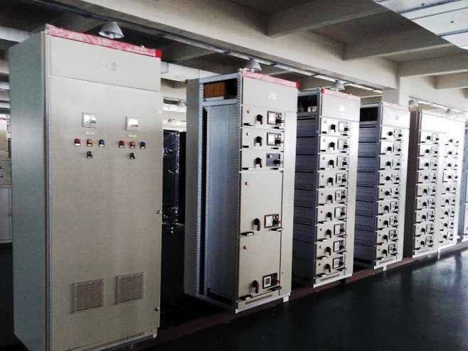
6.Installation Picture

Bibliography
1.Solutions For Enterprise Micro-grid System 2021.04